DIY grounding installation
The location is chosen so that there are no communications on the site. Before making grounding at the dacha with your own hands, coordinate the scheme with the water supply, gas service and other offices. Grounding is done more often on the north side of the house , since there is always a more humid place on the site.
Mount the circuit according to the rules:
- dig a trench for horizontal connections;
- pins are hammered into the corners of a triangle with equal sides;
- You cannot dig holes for the rods; the rods must fit tightly into the ground;
- weld the strip to the corners, attach a conductive cable going to the building;
- After joining, welding areas are treated with melted bitumen (resin);
- bury the installation site.
The circuit is connected to the panel according to the selected circuit; zero and phase are used for input. The two-wire line serves as both a working conductor and a protective conductor. An additional bus is placed inside the shield, in contact with the housing, to combine all the wires.
Check grounding using a multimeter . The socket is opened in the house, the device is switched to voltage regulation. After connecting the zero and phase probes, the multimeter should show voltage. Then the phase and ground are connected, and the voltage should drop slightly.
Monitoring the status of protective devices
Electrical installation rules require periodic testing of the grounding system. It allows you to establish compliance of the parameters of the resistance to current drainage of the grounding loops with the normative ones. The test takes place using special measuring instruments connected to grounding devices according to certain circuits.
The rules also regulate the frequency of inspections. It depends on the inspection class, the design of grounding devices, the type and power of the equipment used. A visual inspection of the condition of the grounding system should be carried out every six months. Inspections accompanied by excavation of the soil in areas associated with increased risk - once every 12 years or more often.
A competent approach to organizing the grounding system for electrical installations, a clear understanding of the structure and features of different types of installations, as well as timely monitoring of their condition, in accordance with current regulations, will ensure the safety of enterprise employees, the safety of equipment and buildings.
What household appliances need to be grounded in the house?
Most household electrical equipment is a source of increased risk of electric shock in the home. To completely eliminate possible risks, it is necessary to ground washing machines, electric and induction cookers, microwave ovens, personal computers, and boilers. The safety of boilers should be given the utmost attention. Water is the best conductor of electricity. Violation of the boiler insulation will lead to the fact that a person touching the water heater will receive an electric shock. The mounted ground will absorb most of the current. The contact of a phase with a grounded boiler tank leads to instantaneous operation of the circuit breaker.
Figure No. 2. Wiring diagram in the apartment
Operation of a difavtomat in a two-wire circuit
The operating principle of a differential device is reminiscent of an analyzer that compares the indicators of currents flowing through the phase and neutral conductors. If deviations in values occur due to a leak (for example, after a short circuit to the refrigerator body), the relay contacts of the difavtomat open and the network is de-energized.
As an example, let’s look at a situation where the insulating layer of the electrical wiring in a washing machine was damaged. Touching a bare current-carrying conductor to a metal casing causes current to spread where it should not exist. As soon as a person touches the washing machine, he will get an electric shock. Moreover, the victim will remain under tension as long as he touches the body (and it is difficult to tear himself away from it). In such a situation, an RCD or automatic circuit breaker comes to the rescue, turning off the current in the circuit.
Useful video on the topic
A lot of interesting information is in the video.
Leave a comment Cancel reply
Related Posts
How to select and connect a differential circuit breaker An outdoor waterproof socket is an important attribute of your site
German ABB sockets combine reliability and stylish design. How to choose a hidden wiring socket, practical advice.
Common Mistakes
The ability to connect a ground wire to metal structures in the ground can have bad consequences if the restrictions are not taken into account.
Grounding is dangerous in the following cases:
- the cable is connected to the water supply system or heating pipes - this is dangerous for the owners of the house and neighbors;
- do not connect the grounding conductor to the neutral contact in the socket - if the neutral burns out, high voltage will be detected on the boxes of all electrical appliances;
- It is not recommended to connect more than one wire to the PE terminal - if electricity is lost, it will not go into the ground through the protective grounding conductor, but will go to household appliances connected by another wire.
It cannot be connected to water supply or heating in the ground also because the system may contain inserts that do not conduct electricity (plastic, polypropylene).
RCD selection
The circuit breaker is designed to operate with an overload for seconds or even minutes. The protective connection device is not able to withstand such loads and will most likely fail. Small power devices are used with a current of 10 Amps or less. For powerful devices you will need a reserve of 40 Amps.
If the voltage in the living room is 220 Volts, buy a two-pole device. For 380 Volts, a four-pole device is required.
The leakage current indicator of the residual current device determines which device is needed: fire protection or current protection. The devices are capable of operating at different speeds. For fast response, selective devices are used, which come in two classes (S and G). Devices marked with the letter G have the highest response speed.
The machines are available in electronic or electromechanical versions. For electromechanical devices there is no need for additional power supply.
As for the type of leakage current, information about this is indicated on the housing. AC stands for alternating current, and A indicates both alternating and direct current.
Preparing materials for the circuit
It is not recommended to use reinforcement for pins, especially ribbed ones.
Such elements quickly oxidize, and the distribution of leakage current occurs unevenly. Materials prepared for the device:
- three grounding rods for vertical placement, a corner would be better;
- three metal strips for horizontal jumpers;
- a metal strip along the length of the distance between the connection point with the circuit and the distribution cabinet (cross-sectional area - not less than 16 mm²).
To fix the grounding conductor to the shield, bolts are used. To divide the wiring into phase and neutral, you need an electrical cable, the cross-section of which is determined by calculation. The wire is also required for the installation of an internal grounding loop.
All elements in the ground are connected only by welding, so you will need a device, electrodes or welding wire (depending on the type of unit). Bolted joints quickly oxidize when wet, so the ground loop ceases to perform its function.
How to calculate grounding for a private house
The calculation method assumes that the person has a technical engineering education. Many physical and mathematical formulas, coefficients and expressions are used to fully take into account all kinds of factors and conditions of use.
When calculating the formulas use the following values :
- number of grounding rods;
- indicators of soil electrical resistance;
- type of grounding electrodes, their dimensional parameters and thickness.
One of the formulas used to calculate the vertical pin is Rb = 0.366 (P/L) Lg (4L/D), where:
- P—resistivity;
- L—electrode length;
- D is the diameter of the electrode.
If a corner is used, then D is taken at the level of 0.95b, where b is the width of the shelf. For a strip, the diameter is 0.5b, where b is the width of the strip. Calculations are carried out with great accuracy to ensure safety.
Based on the calculations, a working diagram is drawn up, in which the immersion points of the rods, the distance between them, and the connection by horizontal elements are indicated. For electricians, the diagram is presented in such a way that it is possible to distinguish all the places where the terminals are connected and insert them into the panel.
A little theory
To increase performance, the design of the pump can be changed.
Structural diagram of parallel connection of pump wheels
With a parallel connection, each impeller delivers only part of the total flow, creating a full head, the flow in the pump is divided into a number of parallel jets. Such pumps are called multi-flow.
When entering the pump, the flow is divided into two parts and enters the impeller from both sides. The impeller in this case is a combination in one part of two impellers located symmetrically relative to the plane normal to the axis of the pump. When leaving the impeller, both parts of the flow are reconnected and enter the spiral outlet.
The design of such a pump is very compact.
Structural diagram of a series connection of pump wheels
With a series connection, each impeller produces only a portion of the total head at full flow, the pump head increases in steps.
This type of design allows you to increase the pump pressure as many times as it has stages. All wheels are mounted on a common shaft and form a single pump rotor.
The axial pressure balancing system, bearings, and seals are combined in one housing common to all stages, which makes the pump compact, reduces weight and reduces cost.
Diagram of a deep and submersible pump
A connection diagram for a submersible pump is needed to see in what order all the parts are connected.
The first step is to determine the depth of the well. The depth of the well is determined by the depth of groundwater. It must be remembered that the distance from the bottom of the well to the pump must be at least 1 meter. The distance from the top point of groundwater to the surface of the earth is called the dynamic level.
To ensure uninterrupted all-season use of the well, a special well - a caisson - is equipped. The depth of the caisson must be no less than the depth of soil freezing.
1. The pipe coming out of the well into the caisson is trimmed and connected to a pipe laid in a trench leading to the house. Thus, the pipeline located in the trench leading to the house must be located at a depth no less than the depth of soil freezing - i.e. at the level of the lower boundary of the caisson. It is recommended to lay two pipes in this trench: the first is for water supply, the second is for electrical wiring.
A coarse filter must be installed directly in front of the pressure control unit and the hydraulic accumulator. Additionally, the same filter is installed at the outlet of the hydraulic accumulator before supplying water to the pipeline system of the house, but this requirement is advisory in nature.
2. Next, you need to connect the power supply to the pump. The wires are connected according to the electrical diagram for connecting the pump. The pump control panel is installed in the boiler room of the house.
Electrical diagram for connecting the pump
Connecting the pump directly to the power supply risks rapid breakdown of the centrifugal unit, and the main reason is that the pump will continue to idle even when the water level drops. For household water supply systems, the correct option is to include factory automation units in the water supply scheme. Such units are called pump control stations or hydraulic controllers.
Appendix: project in DWG and PDF formats
Files in DWG and PDF formats are available for downloading only to authorized users.
Do you need to complete a grounding and lightning protection project? Order it by contacting the ZANDZ.ru Technical Center!
Still have questions about this calculation? Ask it in the comments to this page!
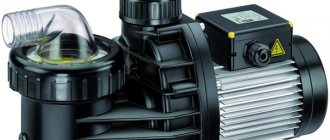
Boost pump STI CRP 15/9
Boost pumps STI
designed to increase pressure in an existing water supply system. Used in the water supply network to increase water pressure in the shower or at other water supply points, in front of water heaters (gas water heaters, instantaneous water heaters, double-circuit boilers), washing machines and dishwashers
Operating principle of ground electrodes
Actually, the ground electrode is a set of conductors that are interconnected and located in the ground at different depths.
Depending on the point of placement of the rods, a distinction is made between loop and remote grounding.
- For the second option, the set of grounding conductors is completely removed outside the house or apartment.
- The first option is characterized by the location of grounding loops around the perimeter of the residential area.
The positive effect in this case is achieved by the uniform distribution of electrical potential over a certain area.
Ground loop
Grounding means the intentional connection of a network point, electrical appliance, household equipment with a ground loop.
In electrical engineering, this is how voltage is reduced when touching live parts to levels that are safe for humans. Performed using a grounding conductor, which is in direct contact with the ground, and a conductive wire. Operating principle of grounding installations:
- reduction of potentials between conductive parts and other conductors with natural grounding;
- removal of leaking electricity when a conductive element and a phase come into contact; in properly designed systems, an RCD is immediately triggered;
- initiation of fuse response upon contact of phase and ground electrode (in circuits with solidly grounded neutrals).
The efficiency of the circuit increases when used in conjunction with residual current devices. This way, the potential on the grounded parts will be optimal and safe, and the faulty section will quickly be de-energized.
Types of contours
Electrical network grounding conductors have similar structures regardless of the number of phases. There is an option to use conductors made of steel angles and rods immersed in the ground to a depth of 2 - 3 m. The jumpers are placed at a height of no more than half a meter to ground level. A current-carrying cable is welded to one horizontal jumper, which goes to the surface.
Design types:
- linear , when two or more vertical pins are connected in series along lengthwise by jumpers;
- closed if 3 or 4 corners are driven in, which are connected along the contour by connections in the shape of a triangle or square.
The linear type loses in terms of effectiveness. When a jumper or vertical element is corroded, the quality of grounding decreases, but in a closed version, all elements complement each other, even if one pin is damaged. You can purchase a factory kit with a tested and carefully calculated design.
The simplest grounding involves connecting to structures located in the ground. These can be metal pipes, grilles, steel devices that can divert leaking current from household appliances.
Valera
The voice of the construction guru
Ask a Question
There is an option for an electrolytic ground electrode. It is used in dry soils, such as sand, where there is high resistance to spreading. They use a single corner in the shape of the letter L, which is filled with a special composition of mineral salts when buried. These are best used in special conditions.
Requirements
The characteristics of the circuit depend on the resistance to the spreading current, which shows how easily the electric current will overcome the distance from the box of household appliances and go into the ground if necessary. The indicator depends on the type of metal, the depth of immersion of the rods, humidity and much more.
Regulatory requirements for grounding circuits :
- the structure is made of individual rods that conduct current;
- use only copper or steel, but not aluminum and other metals;
- minimum metal thickness - 4 mm;
- the minimum diameter of iron pipes is 32 mm;
- the pins are connected by welding into one circuit with a continuous network;
- if a natural system is used, then the conductor is connected at at least two points.
For the natural system, iron structures of buildings located underground, foundations with reinforcement and waterproofing are used. Metal well casing pipes are also allowed to be used. The rails of a railway track are suitable, if it is not electrified, jumpers are placed between the rails.
How does a centrifugal pump with an electric motor work?
The diagram below shows the structure of the internal part of a centrifugal pump and its connection to an electric motor. In the body, pos. 1, which has the shape of a snail, contains an impeller, and blades are located on it. These elements are located on the motor shaft. The suction and pressure pipelines are connected to the discharge and inlet openings. The water that fills the pump, under the action of the centrifugal force arising from the rotation of the impeller by its blades, is thrown into the pressure pipeline from the housing. When the impeller rotates, a vacuum is created in the suction pipe of the device, due to which water continuously flows into the suction pipe.
Tip: Centrifugal pumps can only operate when the impeller, and therefore the suction pipe, is filled with water. Therefore, to retain water inside the pump when it is stopped, a receiving device having a check valve must be installed at the suction end of the pipeline.
If an electric centrifugal pump is put into operation for the first time after completion of installation work or repairs, it is necessary to first fill its housing with water. In this case, you need to ensure that there are no air pockets. The main indicators of pump operation are:
- Performance.
- Pressure
When choosing centrifugal pumps with an electric motor, you need to pay attention that its performance must correspond to the hourly flow rate of liquid in the system, and the pressure must be sufficient to raise the water to the required height and be able to overcome the resistance of pipelines and fittings.