Many people associate electric heating of a home with the installation of appropriate water boilers with heating elements, convectors, or laying heated film floors. However, there are many more options. In modern private homes, electrode or ion boilers are installed, in which a pair of primitive electrodes transfer energy to the coolant without any intermediaries.
Ion-type heating boilers were first developed and implemented in the Soviet Union to heat submarine compartments. The installations did not cause additional noise, had compact dimensions, there was no need to design exhaust systems, and they effectively heated sea water, which was used as the main coolant.
The heat carrier, which circulates through the pipes and enters the working tank of the boiler, comes into direct contact with the electric current. Ions charged with different signs begin to move chaotically and collide. Thanks to the resistance formed, the coolant heats up.
- 1 History of appearance and principle of operation
- 2 Characteristics: advantages and disadvantages
- 3 Design and technical characteristics
- 4 Video guide
- 5 Simple DIY ion boiler
- 6 Features of installation of ion boilers
- 7 Manufacturers and average cost
History of appearance and principle of operation
Within just 1 second, each of the electrodes collides with the others up to 50 times, changing its sign. Thanks to the action of alternating current, the liquid does not divide into oxygen and hydrogen, maintaining its structure. An increase in temperature entails an increase in pressure, which forces the coolant to circulate.
To achieve maximum efficiency of the electrode boiler, you will have to constantly monitor the ohmic resistance of the liquid. At classic room temperature (20-25 degrees), it should not exceed 3 thousand Ohms.
Do not pour distilled water into the heating system. It does not contain any salts in the form of impurities, which means you should not expect it to be heated in this way - there will be no environment between the electrodes to form an electrical circuit.
Read additional instructions on how to make your own electrode boiler here
What is an overheat sensor
In addition to the draft sensor, there is also an overheat sensor. It is a device that protects water heated by the boiler from boiling, which occurs when the temperature rises above 100 degrees Celsius.
When triggered, such a device turns off the boiler. The overheat sensor only works properly if installed correctly. An increase in water temperature without this device would threaten the failure of the gas boiler.
The overheating sensor monitors the temperature increase in the heating circuit. It is installed at the outlet of the heating circuit heat exchanger. When the critical temperature is reached, it opens the contacts and turns off the boiler.
Reasons for triggering the overheating sensor:
- Such a device can work if the water in the column heats up too much;
- If the sensor contact is poor;
- Due to its malfunction;
- If the sensor has poor contact with the pipe.
In order to make the heating sensor more sensitive, heat-conducting paste is used. When overheating, the sensor blocks the operation of the boiler. Modern devices are able to indicate a fault code on the display.
Characteristics: advantages and disadvantages
An ion-type electrode boiler is characterized not only by all the advantages of electric heating equipment, but also by its own characteristics. The extensive list includes the most significant:
- The efficiency of installations tends to the absolute maximum – not less than 95%
- No pollutants or ion radiation harmful to humans are released into the environment
- High power in a housing that is relatively small in size compared to other boilers
- It is possible to install several units at once to increase productivity, or separate installation of an ion-type boiler as an additional or backup heat source
- Low inertia makes it possible to quickly respond to changes in ambient temperature and fully automate the heating process through programmable automation
- There is no need to install a chimney pipe
- The equipment is not harmed by an insufficient amount of coolant inside the working tank
- Voltage surges do not affect heating performance and stability
You can find out how to choose an electric boiler for heating here
Of course, ion boilers have numerous and very significant advantages. If you do not take into account the negative aspects that arise more often during the operation of the equipment, all benefits are lost.
Among the negative aspects it is worth noting:
- To operate ion heating equipment, you cannot use DC power sources, which will cause electrolysis of the liquid
- It is necessary to constantly monitor the electrical conductivity of the liquid and take measures to regulate it
- It is necessary to ensure reliable grounding. If it breaks down, the risk of being shocked increases significantly
- It is prohibited to use heated water in a single-circuit system for other needs.
- It is very difficult to organize efficient heating with natural circulation; installation of a pump is mandatory
- The temperature of the liquid should not exceed 75 degrees, otherwise the consumption of electrical energy will increase sharply
- Electrodes wear out quickly and need to be replaced every 2-4 years
- Repair and commissioning work cannot be carried out without the involvement of an experienced technician.
Read about other methods of electric heating at home here
Difficulties in operation
During use, the consumer may encounter some problems characteristic of electrode heaters:
- The quality of the coolant plays an important role. The service life of the product and reliability of operation depend on this. The use of tap fluid can lead to increased corrosion of metal pipes and radiators and a decrease in efficiency. Manufacturers recommend that owners of electrode boilers use ready-made compositions that have the necessary physical and chemical characteristics. The liquid changes its properties over time, so after 3-4 years the system needs to be filled with fresh coolant.
- It is necessary to pay attention to ensuring the electrical safety of the unit. The body of the device is connected to the neutral cable, the phase is connected to the electrodes. During installation, grounding must be provided. Electric boilers create a large load on the network, so before installing the heating device you should make sure that the wiring is reliable throughout the room.
- Under the constant influence of current, the processes of electrocorrosion of steel and cast iron are accelerated, which reduces the service life of the system several times. Aluminum or bimetallic communications and radiators should be used with electrode units. To provide heat to a cottage or home, you need to make sure that the elements of the heating system are made of recommended materials.
Device and technical characteristics
The design of the ion boiler, at first glance, is complex, but it is simple and not forced. Externally, it is a seamless steel pipe, which is covered with a polyamide electrical insulating layer. Manufacturers have tried to protect people as much as possible from electric shock and leaks of expensive energy.
In addition to the tubular body, the electrode boiler contains:
- The working electrode, which is made of special alloys and is held in place by protected polyamide nuts (in models operating from a 3-phase network, three electrodes are provided at once)
- Coolant inlet and outlet pipes
- Ground terminals
- Terminals supplying power to the chassis
- Rubber insulating pads
The shape of the outer body of ion heating boilers is cylindrical. Most common household models meet the following characteristics:
- Length – up to 60 cm
- Diameter – up to 32 cm
- Weight - about 10-12 kg
- Equipment power – from 2 to 50 kW
For domestic needs, compact single-phase models with a power of no more than 6 kW are used. There are enough of them to fully provide heat to a cottage with an area of 80-150 sq. m. For large industrial areas, 3-phase equipment is used. A 50 kW installation is capable of heating a room up to 1600 sq. m.
However, the electrode boiler works most efficiently in conjunction with control automation, which includes the following elements:
- Starter block
- Surge protection
- Controller
Additionally, GSM control modules can be installed for remote activation or deactivation. Low inertia allows you to quickly respond to temperature fluctuations in the environment.
Due attention should be paid to the quality and temperature of the coolant. The optimal liquid in a heating system with an ion boiler is considered to be heated to 75 degrees. In this case, power consumption will correspond to that specified in the documents. Otherwise, two situations are possible:
- Temperature below 75 degrees - electricity consumption decreases along with the efficiency of the installation
- Temperature above 75 degrees - electricity consumption will increase, however, the already high efficiency indicators will remain at the same level
Rating of the best manufacturers
Many foreign and Russian companies produce ion heaters.
The following manufacturers have the best combination of characteristics:
- Galan is a Russian company offering a wide range of boilers of different capacities. The devices are low cost and reliable. Disadvantages - expensive branded coolant and a stepwise power control system.
- EOU is a Ukrainian brand. The company produces equipment with power from 1 to 36 kW. The declared service life of the products is 30 years. Disadvantages of boilers are high prices, frequent problems with automation.
- “Coterm” is a Russian company engaged in the production of electrical equipment. It produces devices characterized by fast heating of the working fluid, high-quality assembly and compact dimensions. Typical disadvantages are the limited functionality of the automation, the need to fill the heating system with its own Coterm Eco coolant.
- Beril is a Latvian company whose products stand out for their reliability and advanced functionality. The automation system is equipped with several operating modes, degree-by-degree power adjustment, and overheating protection. Provision is made for connecting a GSM module and external temperature sensors. The main disadvantage is the high cost.
- Buderus is a German brand that produces a wide range of gas equipment. The devices are distinguished by their reliability and long service life. Among the electrode models there are two- and three-phase units. The main disadvantage is the price, which is higher than that of Russian devices.
Simple DIY ion boiler
Having become familiar with the features and principle by which ion heating boilers operate, it is time to ask the question: how to assemble such equipment with your own hands? First you need to prepare the tools and materials:
- Steel pipe with a diameter of 5-10 cm
- Ground and neutral terminals
- Electrodes
- Wires
- Metal tee and coupling
- Persistence and desire
Before you start putting everything together, there are three very important safety rules to remember:
- Only the phase is supplied to the electrode
- Only the neutral wire is supplied to the housing
- Reliable grounding must be provided
To assemble an ion electrode boiler, just follow the following instructions:
- First, a pipe 25-30 cm long is prepared, which will act as a body
- Surfaces must be smooth and free of corrosion, nicks at the ends must be cleaned
- On the one hand, electrodes are installed using a tee
- A tee is also necessary to organize the outlet and inlet of the coolant
- On the second side they make a connection to the heating main
- Install an insulating gasket between the electrode and the tee (heat-resistant plastic is suitable)
- To achieve a tight seal, the threaded connections must be precisely adjusted to each other.
- To secure the zero terminal and grounding, 1-2 bolts are welded to the body
Having put everything together, you can embed the boiler into the heating system. Such homemade equipment is unlikely to be able to heat a private home, but for small utility areas or a garage it will be an ideal solution. You can cover the installation with a decorative casing, while trying not to restrict free access to it.
Control methods
Today, a variety of sensors allows the use of various control methods. For example, to control the combustion process of fuel in a liquid or gaseous state, direct and indirect control methods can be used. The first method includes methods such as ultrasonic or ionization. As for the second method, in this case the flame control relay sensors will monitor slightly different quantities - pressure, vacuum, etc. Based on the data received, the system will conclude whether the flame meets the specified criteria.
For example, in small gas heaters, as well as in domestic heating boilers, devices are used that are based on photoelectric, ionization or thermometric flame control methods.
Features of installation of ion boilers
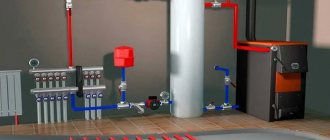
A prerequisite for installing ion heating boilers is the presence of a safety valve, pressure gauge and automatic air vent. The equipment must be placed in a vertical position (horizontal or at an angle are not allowed). At the same time, about 1.5 m of supply pipes are not galvanized steel.
The zero terminal is usually located at the bottom of the boiler. A grounding wire with a resistance of up to 4 ohms and a cross-section of over 4 mm is connected to it. You should not rely solely on RAM - it cannot help with current leakage. The resistance must also comply with the rules of the PUE.
If the heating system is completely new, there is no need to prepare the pipes - they must be clean inside. When the boiler crashes into an already operating main, it is necessary to flush it with inhibitors. The markets offer a wide range of products for removing deposits, salts and scale. However, each manufacturer of electrode boilers indicates those that it considers best for its equipment. Their opinion should be followed. By neglecting flushing, it will not be possible to establish the exact ohmic resistance.
It is very important to select heating radiators for the ion boiler. Models with a large internal volume are not suitable, since 1 kW of power will require more than 10 liters of coolant. The boiler will constantly work, wasting some of the electricity in vain. The ideal ratio of boiler power to the total volume of the heating system is 8 liters per 1 kW.
If we talk about materials, it is better to install modern aluminum and bimetallic radiators with minimal inertia. When choosing aluminum models, preference is given to primary type material (not remelted). Compared to the secondary one, it contains fewer impurities, reducing the ohmic resistance.
Cast iron radiators are the least compatible with an ion boiler, since they are the most susceptible to contamination. If it is not possible to replace them, experts recommend observing several important conditions:
- The documents must indicate compliance with the European standard
- Installation of coarse filters and sludge traps is required
- Once again, the total volume of coolant is produced and equipment suitable in terms of power is selected
Sensor, indicator of combustion, flame, fire, torch. Ignition, fuse, spark igniter. Scheme.
Flame presence indicator combined with an igniter on one electrode (10+)
Flame sensor and spark igniter on one electrode
| 1 | 2 |
Contents :: SearchSafety :: Help
For a gas burner I needed a spark ignition system and a fire indicator. Moreover, I really wanted the same electrode placed in the flame to operate both devices.
When developing the scheme, the following difficulties arose. Firstly, the gas burns without any serious glow. So it is not possible to use a photoresistor. I settled on using the effect of one-way plasma conductivity (the torch torch is the real plasma). To determine the presence of this effect, and, accordingly, the presence of a flame, it is necessary to place an electrode in the fire. An electrode is also needed for the spark discharge of the fuse. There is a temptation to use the same electrode. But, secondly, the direct approach of switching one electrode from the spark transformer to the sensor does not work, since I was unable to find a switch capable of withstanding several tens of kilovolts in igniter mode without piercing them to the sensor.
So we had to take a somewhat roundabout route. I connect the fire sensor in series with the ignition coil. During the fuse, I short-circuit the sensor. After switching to monitoring mode, the normally open contacts open. Voltage to control the flame is supplied to the electrode through the ignition coil. However, with its not very high inductance, it does not interfere with the passage of electric current with a frequency of 50 Hz from the network.
Here is a selection of materials:
The practice of electronic circuit design. The art of device development. Element base. Typical schemes. Examples of finished devices. Detailed descriptions. Online payment. Opportunity to ask questions to the authors
Description of the device
In addition to the fact that flame control sensors ensure the safe operation of the firebox, they also take part in igniting the fire. This stage can be carried out automatically or semi-automatically. While operating in the same mode, they ensure that the fuel burns in compliance with all required conditions and protection. In other words, the continuous operation, reliability, and safety of combustion furnaces completely depend on the correct and trouble-free operation of the flame control sensors.
What to follow
When asked how to choose a heating boiler, they often answer that the main criterion is the availability of a particular fuel. In this context, we will highlight several types of boilers.
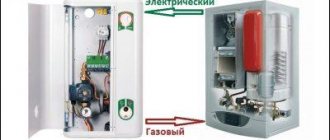
Gas boilers
Gas boilers are the most common types of heating equipment. This is due to the fact that fuel for such boilers is not very expensive and is available to a wide range of consumers. What types of gas heating boilers are there? They differ from each other depending on what type of burner is atmospheric or inflatable. In the first case, the exhaust gas goes through the chimney, and in the second, all combustion products escape through a special pipe using a fan. Of course, the second version will be a little more expensive, but it will not require smoke removal.
Wall-mounted gas boiler
As for the method of placing boilers, the choice of heating boiler involves the presence of floor and wall models. Which heating boiler is better in this case - there is no answer. After all, everything will depend on what goals you are pursuing. If, in addition to heating, you need to supply hot water, then you can install modern wall-mounted heating boilers. This way you won’t need to install a boiler to heat the water, and this will save money. Also, in the case of wall-mounted models, combustion products can be discharged directly onto the street. And the small size of such devices will allow them to fit perfectly into the interior.
The disadvantage of wall-mounted models is their dependence on electrical energy.
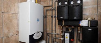
Electric boilers
Next, we will consider electric heating boilers. If there is no mains gas in your area, an electric boiler can save you. These types of heating boilers are small in size, so they can be used in small houses, as well as in cottages with an area of 100 sq.m. All combustion products will be harmless from an environmental point of view. And installation of such a boiler does not require special skills. It is worth noting that electric boilers are not very common. After all, fuel is expensive, and its prices are rising and rising. If you are asking which heating boilers are better in terms of economy, then this is not an option in this case. Very often, electric boilers serve as backup heating devices.
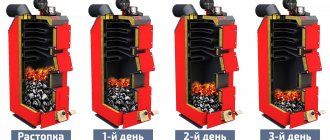
Solid fuel boilers
Now it’s time to consider what solid fuel heating boilers are available. Such boilers are considered the most ancient; such a system has been used for heating premises for a long time. And the reason for this is simple - fuel for such devices is available, its quality can be firewood, coke, peat, coal, etc. The only drawback is that such boilers are not able to operate in autonomous mode.
Gas generating solid fuel boiler
A modification of such boilers is gas generator devices. This boiler differs in that it is possible to control the combustion process, and the productivity is regulated within the range of 30-100 percent. When you are thinking about how to choose a heating boiler, you should know that the fuel that such boilers use is wood, and their humidity should not be less than 30%. Gas fired boilers depend on the supply of electrical energy. But they also have advantages over solid fuel ones. They have high efficiency, which is two times higher than solid fuel devices. And from the point of view of environmental pollution, they are environmentally friendly, since combustion products will not enter the chimney, but will serve to generate gas.
The rating of heating boilers shows that single-circuit gas generator boilers cannot be used for heating water. And if we consider automation, it is great. You can often find programmers on such devices - they regulate the temperature of the coolant and give signals if there is an emergency.
Gas generator boilers in a private home are an expensive pleasure. After all, the cost of a heating boiler is high.
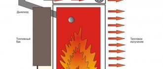
Liquid fuel boilers
Now let's look at liquid fuel boilers. Such devices use diesel fuel as a working resource. To operate such boilers, you will need additional components - fuel containers and a room specifically for the boiler. If you are thinking about which boiler to choose for heating, then we note that liquid fuel boilers have a very expensive burner, which can sometimes cost as much as a gas boiler with an atmospheric burner. But such a device has different power levels, which is why it is profitable to use it from an economic point of view.
In addition to diesel fuel, liquid fuel boilers can also use gas. For this purpose, replaceable burners or special burners are used that can operate on two types of fuel.
Liquid fuel boiler
Calculation of power for the area of the house
We present a simplified calculation of power, since this issue is a topic for a separate article. Approximate calculation usually always gives results as close as possible to real needs.
If the electric boiler performs an auxiliary heating function in addition to the main gas or other unit, or fireplace, then for 120–150 m² a power of 3–6 kW will be sufficient.
Comparative table of average statistical electricity consumption by electric boilers
| Boiler power | Heating area, m² | Consumption, kW/hour | Boiler power | Heating area, m² | Consumption kW/hour |
| 3 kV 1 phase | 50 | 0.5–0.6 | 3 kV 1 phase | 30 | 1.5–1.8 |
| 5 kV 1 phase | 80 | 0.9–1.2 | 5 kV 1 phase | 50 | 2.0–2.5 |
| 9 kV 3-phase | 120 | 1.8–2.3 | 9 kV 3-phase | 90 | 3.6–4.2 |
| 25 kV 3-phase | 350 | 4.5–5.5 | 25 kV 3-phase | 240 | 9.5–11.0 |
If an energy-saving boiler is the main source of heat, then it is necessary to carry out calculations taking into account heat losses, which for an average private home with two-brick masonry and 2.7 m ceilings in the climate of the Moscow region is 1 kW/hour. It is recommended to select power with a margin of 10–20%, and for heating element heaters - by 20–30%, since their efficiency decreases due to scale. For 80 m² you will need an electric boiler of 9.6–10 kW (8 kW + 20%).
For SAV boilers, a power of 2.5 kW is 2100 kcal/hour, which is enough to heat 25–30 m². The calculation is affected by the required temperature. If you need to maintain 15–20 degrees in a room of 120 m², then a 6 kW unit will suffice.
An economical ion-type electric heating boiler with a power of 3 kW is suitable for heating 50 m². The same product with a heating element will heat 30 m².
Burner control
LAE 10, LFE10 devices have become fairly common burner flame control sensors. As for the first device, it is used in systems that use liquid fuel. The second sensor is more versatile and can be used not only with liquid fuel, but also with gaseous fuel.
Most often, both of these devices are used in systems such as a dual burner control system. Can be successfully used in liquid fuel blower gas burner systems.
A distinctive feature of these devices is that they can be installed in any position, and can also be attached directly to the burner itself, on the control panel or on the switchboard
When installing these devices, it is very important to correctly lay the electrical cables so that the signal reaches the receiver without loss or distortion. To achieve this, you need to lay the cables from this system separately from other electrical lines
You also need to use a separate cable for these monitoring sensors.
When using any heating equipment that runs on natural fuels, you should always keep in mind the high risk of ignition or even explosion of this natural flammable substance.
Such a disaster can occur in situations in which a fire or torch may go out due to any reason. If the gas mixture continues to flow into the interior of the unit or the external space around it, one spark from an open flame will be enough for a fire or even an explosion to occur.
The most common cause of such cases is flame separation followed by extinction. This occurs when it is displaced from the outlet in the direction of the flow of the gas mixture. As a result, the firebox fills with gas, which leads to a bang or explosion. The cause of separation is the excess of the mixture flow speed over the fire spread speed.
Guidelines and what to consider when choosing an economical electric heating boiler
An economical electric boiler must have programmable operation, the ability to connect a rheostat for on/off. during periods of low tariffs or when a certain temperature is reached, as well as to regulate heating. At a minimum there should be at least a three-stage power switch.
The ideal option is if the device has smooth adjustment and factory economy modes. The product must be suitable for connection to room rheostats, which have many fine settings and respond to the air temperature in the room.
Single- and double-circuit electric boilers
If you need to provide hot water at the same time as heating, then choose double-circuit electric boilers. Moreover, the electricity consumption in such products is practically no different from single-circuit ones. DHW water is heated by washing the heat exchanger in the heating boiler circuit, without mixing with its coolant. Such heating does not require additional power, although for greater efficiency there are models with increased energy consumption.
Choosing electrode boilers for heating a private house: reviews from owners
When considering a variety of heating system options for a private home, most choose a system with a gas boiler because it is the most economical. However, in addition to the fact that when installing a gas boiler and connecting to the blue fuel supply system for the house, it is necessary that there is a gas pipeline .
So this option is unlikely to be suitable for buildings located at some distance from most communications. In such cases, people often opt for electrode boilers.
Controlling the flame
The presence of open fire is monitored using ionization. The principle of flame control using this process is based on a classical physical phenomenon.
Electrical diagram for connecting the ionization electrode.
When a gas burns, a huge number of freely charged particles are formed - electrons with a minus sign and ions with a plus sign. They are attracted and move towards the ionization electrode and form a small ionization current - literally a few microamps.
The ionization unit is connected to a burner control unit, which is equipped with a sensitive threshold device. It is triggered when a sufficient number of charged electrons and ions are formed - it allows. If the ionization flow decreases and reaches a minimum threshold, the burner instantly turns off.
The ionization flame control electrode is designed quite simply: it consists of a ceramic body and a rod placed in it. The main element is a specialized high-voltage cable with connectors for fastening.
In order for the device to work correctly and for a long time, you must first of all strictly observe the ratio of air and combustible mixture. The second condition for success is keeping the device completely clean.
Methods for controlling the presence of flames when burning gas and liquid fuel in boiler furnaces can be divided into two types: direct and indirect control. Direct control methods include ultrasonic, thermometric, ionization and the most commonly used photoelectric. Methods of indirect control of fuel combustion include monitoring the vacuum in the furnace, the fuel pressure in the supply pipeline, the pressure or difference in front of the burner, and monitoring the presence of a constant ignition source.
Domestic heating boilers, gas heaters and small gas heaters use devices that are based on ionization, photoelectric and thermometric control methods. The ionization control method is based on electrical processes that arise and occur in a flame. Such processes include the ability of a flame to conduct current, rectify alternating current and excite its own emf in electrodes placed in the flame, as well as periodic pulsation of electrical oscillations in the flame, which in all cases is determined by the degree of ionization of the flame.
The photoelectric method of monitoring the combustion of liquid fuel consists of measuring the degree of visible and invisible radiation of the flame using photo sensors with both external and internal photoelectric effects. Methods for controlling the presence of flame have found many design solutions.
Thermoelectric control method. The device, based on the thermoelectric control method, consists of a thermocouple - sensor and solenoid valve. The thermocouple is placed in the combustion zone of the boiler pilot burner, and the solenoid valve is installed on the gas pipeline through which gas is supplied to the pilot burner.
The thermoelectric control device developed by the Mosgazproekt Institute has become widespread. It is used in heating and cooking boilers, gas heating furnaces and water heater tanks. The operating principle of the thermoelectric flame control device is as follows. The pilot burner operates continuously to ensure reliable ignition and operation of the main operating burners. The pilot gas is ignited by a thermocouple and provides protection against flame retardation. The thermocouple produces an emf, which keeps the solenoid valve open.
When the burner flame goes out, the temperature of the thermocouple will drop so much that the emf excited by it. will not be sufficient to hold the armature in the open position, as a result of which the valve, under the action of the spring, will close the flow of gas to the igniter and the boiler burner. Subsequent ignition of the boiler can only be done manually after eliminating the causes caused by the gas supply being turned off.
Ionization control method. The ionization method of flame presence is based on the use of the electrical properties of the flame. Safety devices based on this method have the advantage that they are practically inertia-free, since when the controlled flame goes out, the ionization processes stop, and this leads to an almost instantaneous shutdown of the gas supply to the boiler burners. This method made it possible to develop monitoring devices based on the electrical conductivity of the flame and the occurrence of emf. flame, its valve effect and electrical pulsation. Abroad, the greatest attention is paid to the flame presence control method based on the valve effect.
In combustion safety devices that use this method, no false signal is observed when the sensor circuit is shorted. In the complex automation system for heating boilers, a flame control device was used, the operation of which is based on the valve effect. When there is a flame, the alternating voltage applied between the electrode inserted into the flame and the burner body is rectified.
When the flame goes out, the valve effect in the interelectrode junction stops and the control signal does not arrive at the amplifier input. The right side of the lamp is locked, the relay is de-energized and gives the command to turn off the gas. A similar action will occur when the electrode is shorted to the burner body.
The main disadvantage of the device circuit is that in it the open (working) position of the right part of the triode is ensured by closing its left part. A control method that uses the electric potential of the flame. This method is based on the introduction of metal electrodes into the torch, which give a potential difference (emf), variable in amplitude, but constant in sign. The magnitude of the e.m.f. is proportional to the temperature difference between the electrodes and reaches 2 V. The device was created on this principle. Operating principle of the e.m.f. device is as follows: in the absence of a flame, equal currents flow in the anode circuits of the lamp. The magnetic flux arising in the windings of relays P1 and P2 under the influence of current is zero, since the windings of the polarized relay are connected in opposite directions. In this case, the Relay armature is in a position in which the power supply circuit of the solenoid shut-off valve is broken and gas does not flow into the burner. When a flame appears, a negative emf appears, which is supplied to the grid of the left side of the triode, which leads to a decrease in the current in winding P1. Under the influence of the resulting magnetic field, the relay armature will change its position and, closing the contacts, will give the appropriate command. When the flame goes out or there is a short circuit in the emf sensor circuit. will disappear and the circuit will return to its original position.
A control method using electrical pulsation of the flame. For any torch, regardless of the type of fuel burned and the type of burner device, a characteristic feature is the pulsation of the processes accompanying combustion. Such processes include flame temperature, pressure in the combustion chamber, radiation intensity and ionization of the flame. The frequency and amplitude of the pulsations depend on the rate of flow of the gas-air mixture from the burner and the conditions of mixing the gas with air. If the gas is not mixed with air satisfactorily, combustion is accompanied by separate outbreaks. Using a sensitive galvanometer, you can measure the ripple value of the ionization current. This property of the flame makes it possible to ensure self-control of the automation against a dangerous short circuit in the electrode sensor circuit.
The circuit uses its own pulsating potential that appears on the electrodes. When a direct current source is connected to the ionization sensor circuit, the pulsation on the electrodes can be increased. In any case, if there is a short circuit in the sensor circuit, as well as when the flame goes out, the supply of the control signal to the amplifier input stops, and the automation is activated to turn off the gas. This circuit does not work from a DC signal, since a capacitor is connected at the input of the first stage. Flame monitoring devices of this type, operating on an alternating component of the electrical signal, are very sensitive to interference, the oscillation frequency of which is close to the pulsation frequency of the torch. As a result, when installing such devices at sites, mandatory shielding of the amplifier input circuits and communication lines connecting the electrode sensor to the device is required.
Heating units operating on natural gas (furnaces, boilers, heating stands, etc.) must be equipped with a flame detection system. During the operation of thermal units, situations are possible in which the burner flame (torch) goes out, but the gas will continue to flow into the internal space of the unit and the environment, and in the presence of a spark or open fire, this gas may ignite and even explode. Most often, flame extinction occurs due to torch separation.
The presence of a flame is monitored either using an ionization electrode or a photosensor. As a rule, an ionization electrode is used to control the combustion of the igniter, which, in turn, will ignite the main burner if necessary. Photosensors control the flame of the main burner. A photo sensor is not used to control the igniter flame due to the small size of the igniter flame. The use of an ionization electrode to control the flame of the main burner is not rational, since an electrode placed in the flame of the main burner will quickly burn.
Photosensors vary in sensitivity to different wavelengths of light flux. Some photo sensors react only to the visible and infrared spectrum of light from a burning flame, others perceive only its ultraviolet component. The most common photo sensor that responds to the visible component of the light flux is the PM sensor.
The luminous flux is perceived by the photoresistor of the sensor, and after amplification it is converted either into a 0-10V output signal, proportional to the illumination, or supplied to the winding of a relay, the contacts of which close if the illumination exceeds the set threshold. The type of output signal - a 0-10V signal or relay contacts - is determined by the modification of the PFD. The FDF photo sensor usually works with the F34 secondary device. The secondary device provides power to the PFC with a voltage of +27V; it also sets the operating thresholds if the PFC with a current output is used. In addition, depending on the modification, F34 can monitor the signal from the ionization electrode of the ignition burner, control the ignition and operation of the burner using built-in relays.
The disadvantages of visible light photo sensors include the fact that they react to any light source - sunlight, flashlight light, light radiation from heated structural elements, linings of steel-pouring ladles, etc. This limits their use, for example, in heating stands, since false alarms from the glowing heated lining of the ladle block the operation of the automation (false flame error). FDFs are most widely used in furnaces for drying sand, ferroalloys, etc. - where the heating temperature rarely exceeds 300-400°C, which means there is no glow of heated elements of the furnace structure.
A distinctive feature of ultraviolet photosensors (UPV), for example UVS-1 from Kromschroeder, is that they react only to the ultraviolet component of the light flux emitted by the burner flame. In the luminous flux from heated bodies, structural elements of furnaces, and ladle linings, the ultraviolet component is small. Therefore, the sensor is “indifferent” to extraneous light, just as it is to sunlight.
The basis of this sensor is a vacuum tube - an electron photomultiplier tube. As a rule, these sensors are powered by a voltage of 220V and have a current output signal that varies from 0 to several tens of microamps. The disadvantages of ultraviolet sensors include the fact that the vacuum tube of the photomultiplier tube has a limited service life. After a couple of years of operation, the lamp loses its emissivity and the sensor stops working. The signal from the UVD is transmitted to the IFS series burner control, the functions of which are similar to those of the F34.
Photosensors must have, so to speak, visual contact with the burner flame, so they are located in close proximity to it. As a rule, they are located on the burner side at an angle of 20-30° to its axis. Because of this, they are subject to strong heating by thermal radiation from the walls of the unit and radiation heating through the sight window. To protect the photosensor from overheating, protective glass and forced airflow are used. Protective glasses are made from heat-resistant quartz glass and are installed at some distance in front of the sighting window of the photosensor. The sensor is blown either with fan air (if the burner of the installation operates on fan air) or with compressed air of low pressure. The supplied volume of air cools the photosensor not only due to heat transfer processes, but also due to the fact that an area of high pressure is created around it, which repels the hot air, preventing it from contacting the sensor.
The presence of a pilot flame is monitored in most cases by an ionization electrode. The principle of flame control by ionization is based on the fact that when gas is burned, many free electrons and ions are formed. These particles are “attracted” to the ionization electrode and cause an ionization current of tens of microamps to flow. The ionization electrode is connected to the input of the device for monitoring the presence of ionization (burner control). If, when the igniter flame burns, a sufficient number of free electrons and negative ions are formed, then a threshold device is activated in the combustion control unit, allowing the operation (or ignition) of the main burner. If the ionization intensity drops below a certain level, the main burner is switched off even if it was working normally. The video below shows how, due to the heating of the air between the plates of the capacitor (in our case, one plate is the control electrode, the other plate is the igniter housing), electric current begins to flow in the circuit.
The main reasons for the loss of ionization are the lack of the required gas-air ratio of the igniter, contamination or burning of the ionization (control) electrode. Another reason for the loss of the ionization signal may be a decrease in the resistance between the ionization electrode and the igniter body, which most often occurs due to the deposition of conductive dust on the ignition device.
The burner control device often performs not only the function of monitoring the presence of a flame - the entire automatic control of the burner ignition is based on it, as, for example, it is implemented in the Hegwein company.
As a rule, the ionization electrode is placed along the axis of the pilot burner, the end of the electrode should be at the “root” of the pilot flame. In some ignition devices, the ionization electrode functions as an ignition electrode. In this case, a high voltage is applied to it for a fixed time to ignite the igniter. After the igniter is ignited, the control electrode switches to the ionization control mode - the ignition circuits are turned off and the electrode is connected to the input of the burner control unit. In this case, another possible reason for the loss of the ionization signal is associated with a break in the secondary winding of the transformer. But in this case, the spark may still be generated normally, so this malfunction is sometimes difficult to determine.
The correct gas-air ratio is of great importance for the stable operation of the ignition device. In most cases, the required gas and air pressure values are given by the manufacturer in the pilot burner data sheet. Despite the fact that when they say “gas-air ratio,” in most cases they mean their volumetric ratio (one volume of gas per ten volumes of air), but they adjust the igniter, and the burner, too, by pressure, since this it's much easier and cheaper to do. For this purpose, the design of the igniter provides for the connection of a control pressure gauge to the gas and air path in certain places.
The ionization electrode is attached to the igniter body through a ceramic insulating sleeve and is connected to the input of the burner control unit with a shielded single-core cable. If the ionization electrode is also used as an ignition electrode, then it is connected to the ignition transformer with a special high-voltage cable, for example, PV-1. The insulating sleeve is made of ceramics with a high content of Al2O3, which is characterized by high mechanical strength, temperature resistance and electrical strength up to 18 kV. The ionization electrode is made of canthal, a metal alloy resistant to high temperatures and electrochemical corrosion.
Installations that constantly operate at temperatures above 800°C (open hearth furnaces, for example) may not be equipped with flame detection systems. This is due to the fact that the ignition temperature of the gas is in the range of 645 – 750°C. Thus, in the event of a torch separation, the gas emanating from the burner nozzle will ignite from the heated masonry of the internal space of the heating unit. Very often, a special burner stone is placed in front of the burner nozzle - it ignites the gas flow and stabilizes combustion.
To increase the reliability of operation and reduce the number of plant shutdowns due to loss of ionization, it is possible to make the control of the presence of a flame not constant, carrying it out using the “OR” circuit. In this case, if the installation has warmed up to temperatures above 750°C and the ionization signal from the pilot burner has disappeared for some reason, the main burner will still continue to operate.
You can find more information in the section.
Since furnaces are now widely used in industry to create various types of material, it is very important to monitor its stable operation. To meet this requirement, a flame sensor must be used. A certain set of sensors allows you to control the presence, the main purpose of which is to ensure the safe operation of various types of installations that burn solid, liquid or gaseous fuels.
Electrode heating equipment market
The most common electrode boiler units in Russia are the following brands:
— "GALAN" (Russia);
— "EOU" (SPD-FO O.A. Goncharenko, Ukraine);
— "STAFOR EKO" (Latvia).
Manufacturers provide up to two years of warranty on heating units subject to proper operation. The service life of the boiler itself is more than 10 years with regular replacement of the current electrodes every 3 years.
The approximate cost of a 2 kW heating unit is 9.5–
10 thousand rubles, including the necessary control and automation unit
-
6.5
-
7 thousand rubles.
Galan boiler is a product of conversion developments
The Galan heating unit is produced in accordance with the standards for military equipment, since this device is a conversion development of enterprises that produce devices for heating submarines and warships.
The Galan electrode boiler is a cylinder with a diameter of 60 mm and a length of 310 mm. Current is supplied to the unit using concentric tubular electrodes, then transferred to the coolant. The heated coolant is distributed by a circulation flow through pipes and radiators. In heating systems with Galan electrode devices, the circulation pump serves to accelerate the heating of the coolant, and then it can be turned off.
Advantages of the Galan brand ion boiler:
- presence of a built-in sensor for automatic heating control;
- high efficiency – up to 98%;
- low sensitivity to voltage changes;
- low power consumption;
- no need for approval for installation and use with boiler inspection;
- more compact dimensions than heating elements units;
- low cost - from 250-300 dollars.
A special antifreeze “Potok” was developed for these units. Additives to this liquid slow down the formation of scale on the walls of the device and the occurrence of metal corrosion processes.
When installing the electrical part of the heating circuit with your own hands, you must use the “Instructions” of Glavgosenergonadzor dated March 21, 1994, No. 42-6/8-ET.