For other uses, see Figure (disambiguation).
This article is about diagrams or drawings. For artistic drawing, see Drawing. For other plan types, see Plan (disambiguation).
| This article does not cite any sources . |
Latécoère 28 plan with three views for presentation.
Plans
is a set of drawings or two-dimensional diagrams used to describe a place or object or to convey construction or manufacturing instructions. Plans are usually drawn or printed on paper, but they can be in the form of a digital file.
These plans are used in a variety of fields ranging from architecture, urban planning, landscape architecture, mechanical engineering, civil engineering, industrial engineering to systems engineering.
Review[edit]
Plans are often intended for technical purposes such as architecture, engineering, or planning. Their goal in these disciplines is to accurately and unambiguously capture all the geometric features of an object, building, product or component. Plans may also be intended for presentation or orientation, and as such are often less detailed versions of the former. The ultimate purpose of plans is to either depict an existing site or object or to convey enough information to allow a builder or manufacturer to carry out the project.
The term "plan" can be used to refer to one view, sheet, or drawing in a set of plans. More specifically, a plan view is an orthographic projection looking down at an object, such as a floor plan.
The process of creating plans and the skill of creating them is often called technical drawing. A working drawing is a type of technical drawing that is part of the documentation needed to create an engineering product or architecture. Typically in architecture, these may include civil drawings, architectural drawings, structural drawings, mechanical drawings, electrical drawings, and plumbing drawings. In engineering, these drawings show all the necessary data for the manufacture of a given object, such as dimensions and angles.
Drawing programs
Also, when describing online services for creating a project sketch, one cannot ignore a number of popular programs created specifically for such purposes. However, most of them are paid, since the functionality of free programs may not be enough to solve professional problems.
- Autodesk AutoCAD is one of the most famous computer-aided design (CAD) systems designed for creating various types of drawings, diagrams, and graphs. Allows you to create 2D and 3D drawings at a highly professional level, has rich functionality, copes well with rendering 3D objects, and can work with a 3D printer. Supports working with drawings in DVG, DWF, DXF formats;
- "Askon Compass" is a whole range of software solutions for drawing and diagramming, which are quite popular in the Russian Federation. These solutions support many formats of electronic drawings, have a large database of attached libraries, and are quite simple and easy to use;
- "nanoCAD" is a free program for beginners, which includes the necessary set of basic tools for designing and creating drawings. The program is aimed at creating mainly 2D drawings, supports working with DWG and DXF drawings, the advantage of the program is the fast output of objects, working with DirectX and so on.
Features of the plan[edit]
Format [edit]
Plans are often prepared “as a set”. A set includes all information needed for the purposes of the set and may exclude views or projections that are not needed. The set of plans can be on standard office-size paper or on large sheets. It can be sewn, folded or rolled if necessary. A set of plans can also be in the form of a digital file in a native format such as DWG or an interchange file format such as DXF or PDF.
Plans are often called "blueprints" or "blue lines". However, these terms are quickly becoming an anachronism, as these copying methods have largely been supplanted by reproduction processes that produce black or multi-colored lines on white paper, or by electronic representation of information.
Scale[edit]
Main articles: Architect scale, Engineer scale, and Metric scale
Plans are usually "scale drawings", that is, plans are drawn in specific proportions to the actual dimensions of a place or object. You can use different scales for different designs in the set. For example, a floor plan might be drawn at 1:48 (or 1/4"=1′-0"), whereas a detail view might be drawn at 1:24 (or 1/2"=1′-0"). . Site plans are often drawn in increments of 1" = 20 feet (1:240) or 1" = 30 feet (1:360).
The ratios commonly used in the metric system are 1:5, 1:10, 1:20, 1:50, 1:100, 1:200, 1:500, 1:1000, 1:2000, and 1:5000.
Views and forecasts[edit]
Symbols used to determine whether a projection is third angle (right) or first angle (left).
Comparison of several types of graphic projection.
Because plans represent three-dimensional objects on a two-dimensional plane, the use of views or projections is critical to the clarity of plans. Each projection is achieved by selecting the viewpoint from which a place or object can be seen and the type of projection. These types of projections are:
Classification of plan (drawing) and some 3D projections
- Parallel projection Orthographic projection Multi-channel projection, including: Plan view or floor plan
- Height, usually viewed from the outside
- Section, view of the interior in a certain sectional plane
- Isometric projection
- Single point perspective
Planning approach[edit]
There is no universal standard for sheet order, but the following describes a general approach:
- General Information: The first sheets in the set may include notes, build descriptions, a visualization of the project, or simply the name of the project.
- Website: site plans, including the key plan, appear earlier than other plans, and in small projects they may be on the first sheet. The project may require a landscape plan, although it can be integrated with the site plan as long as the drawing remains clear.
- Specific Plans: Floor plans, starting with the lowest floor and ending with the roof plan, usually appear at the beginning of the set. Further, for example, reflected ceiling plans (RCPs), showing ceiling layouts, appear after floor plans.
- Elevations: Starting with the main elevation or elevation, all building elevations appear after the plans. Smaller residential projects may display elevations ahead of plans. Facade details can be displayed on the same sheets as building facades.
- Sections: Building sections that describe views cut through the entire building appear next, followed by wall sections, and then detail sections.
- Details: Details can appear on any of the previous sheets or can be compiled to appear on detail sheets. These details may include design details that show how the building's components fit together. These details may also include millwork drawings or other interior details.
- Schedules: Many aspects of a building must be specified as schedules for larger projects. This includes specifications for windows, doors, wall or floor finishes, hardware, landscaping, rooms and areas.
If additional systems are complex and require a large number of parts to install, special additional plan drawings may be used, such as:
- Structural: While smaller projects may only show structural information on plans and sections, larger projects have separate sheets describing the structure of the building.
- Mechanical: Mechanical drawings show plumbing, HVAC, or fire protection systems.
- Electrical equipment. Electrical diagram drawings may include equipment and cable tray locations, lighting and power, grounding, telephone, local area network, special communication or alarm systems, or indirect lighting plan.
How to draw diagrams in Word
Before creating diagrams in Word, it would be nice to learn how to change the color of the page, create beautiful frames, and use WordArt.
Open a new document: - Start - Programs -
Microsoft Office - Microsoft Office Word
.
At the bottom of the panel – Drawing
– select the icon –
Rectangle
.
If you do not have this panel, then go to the menu – View – Toolbars –
and select –
Drawing.
After you clicked on the icon - Rectangle
– you will have such a frame.
Click anywhere in the newly created field. The field will look like this.
You can cut out this square in the center (right-click on it and select Cut
-).
Select the rectangle in which we will draw. In the panel – Drawing
– open –
AutoShapes – Basic Shapes – Cube
– and click on the field of the selected rectangle.
You should get a picture like this.
You can move and resize this cube. To do this, click on this cube to select it. If, when you hover your mouse over this cube, the cursor takes the form of a cross with arrows at the ends, then this object can be moved. If the cursor takes the form of a double-headed arrow (at the nodes, which are indicated by small circles), then you can change the size of the object. Make a rectangular shape out of the cube.
Right-click on the new shape and select Copy from the drop-down menu .
.
Then right-click on the free field next to the shape and select – Insert
. Do this trick twice.
You can select the ready-made shapes you need from the panel - Drawing - AutoShapes - Other AutoShapes
.
It should look like this.
Now drag these shapes like I did.
Try to make the next figure yourself (again, using the copying method).
You can also insert small external drawings here, such as icons. Simply take the icon you need and copy or drag it into place. This is what we got.
Now let's sign our drawings. To do this, select the frame with the pictures (click on a space free from the pictures to make a frame appear) and select Drawing
Inscription
icon .
Now click on the free field of the frame. It should look like this.
We have a new small frame with a cursor. We will write in it. The size of this frame can also be changed.
Create the same inscriptions as mine using the copy method and move them to their places.
Now let's draw connecting lines. To do this in AutoShapes
(on the panel –
Drawing
-) select –
Connecting lines
.
Don't forget to select the main frame before choosing. You can call it “ Canvas
”.
After all, we paint on it like on a canvas. Ledge with an arrow
as the connecting line .
This is where you have to be patient and practice. Place the cursor in the form of a cross at the place where you are going to draw the line and click without releasing the left mouse button, drag the line to the place where you want it and only then release the mouse button.
If it doesn’t work, then cancel your action and select the connecting line again and start over. Each new line must be re-selected in the panel – Drawing
.
Lines can be changed by dragging the yellow diamonds on them.
Now let's make a nice background for our drawing. To do this, again select our “canvas” and select the icon on the same panel – Fill Color
.
Having selected the desired color, click on the icon again and make a second click on the free field of the “canvas”. Or first click on the “canvas” and then on the fill icon.
This is what we got.
To prevent our individual pictures and icons from moving in different directions, we need to select each element (and connecting lines too) (click on each element while holding down the Ctrl key
" until all items are selected). Here too you will have to work hard. Even I don’t always succeed the first time.
Now carefully right-click on some selected element (for example, on a monitor icon) and select – Group
–
Group
.
With a little practice, you can quickly and easily create any diagram in Word .
By the way, the thickness of all lines can be changed. To do this, select the required line by clicking on it and select in the panel – Drawing – icon – Line Type
. But this must be done before grouping. Frames with inscriptions can also be filled with any color (this can also be done after grouping).
Many users may need to draw online. This can be any sketch, diagram, plan or technical illustration that needs to be created on a PC using the appropriate tools. At the same time, the computer may not have the programs necessary for this, which will prompt the user to search online for resources that can help in creating the project the user needs. In this material I will tell you how to make a drawing online, and what services will help us with this.
We study online resources for completing the drawing online
See also[edit]
- Architectural drawing
- Drawing
- Engineering drawing
- Floor plan
- House plan
- Plat
| vteVisualization of technical information | |
| Fields |
|
| Image Types |
|
| People |
|
| similar topics |
|
Drawing programs
Also, when describing online services for creating a project sketch, one cannot ignore a number of popular programs created specifically for such purposes. However, most of them are paid, since the functionality of free programs may not be enough to solve professional problems.
- Autodesk AutoCAD is one of the most famous computer-aided design (CAD) systems designed for creating various types of drawings, diagrams, and graphs. Allows you to create 2D and 3D drawings at a highly professional level, has rich functionality, copes well with rendering 3D objects, and can work with a 3D printer. Supports working with drawings in DVG, DWF, DXF formats;
- "Askon Compass" is a whole range of software solutions for drawing and diagramming, which are quite popular in the Russian Federation. These solutions support many formats of electronic drawings, have a large database of attached libraries, and are quite simple and easy to use;
- "nanoCAD" is a free program for beginners, which includes the necessary set of basic tools for designing and creating drawings. The program is aimed at creating mainly 2D drawings, supports working with DWG and DXF drawings, the advantage of the program is the fast output of objects, working with DirectX and so on.
Material calculation
If designing doesn't interest you, or all you need is to calculate the amount of materials that will be needed to build a house, garage or other structure, then mastering the use of complex software is not at all necessary. To solve such problems, there are many free interactive services (construction calculators) that can be found through any search engine. They will help you plan the purchase of the necessary materials.
You can learn more about the capabilities of simple software for designing building structures by reading the opinions of FORUMHOUSE users in a special section of our website. After reading the lessons on designing houses using the Google SketchUp 8 computer application, you will easily learn how to work in one of the most popular programs for 3D modeling of houses, plots and interiors. A thematic video from FORUMHOUSE will help you understand why a properly designed house allows the future owner to receive a lot of advantages during construction.
Object-planning solutions for the project
Make a list of the required premises and their quantity. It may include:
- living room;
- bedroom;
- kitchen;
- hallway;
- toilets and bathrooms;
- utility rooms and storage rooms;
- boiler room;
- cabinet;
- billiard room, etc.
Decide what will be located and on what floor. Below are practical recommendations on how to correctly draw a house plan in compliance with optimal dimensions and positioning, so that the residence of family members is as convenient and comfortable as possible.
To make the right house layout yourself, you need to not only adhere to design rules. In addition, you will need to apply knowledge of architects and design.
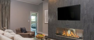
Living room
This is usually the largest room on the first floor. The living room area is designed depending on the number of guests living and frequently visiting, but plan it to be at least 18 m2. Often a fireplace is built here and a large TV is installed. The panoramic glazing looks beautiful with a view of the green area of the site and a passage to the terrace. Doors from bedrooms, toilets, bathrooms and other private or utility rooms should not open directly into the living room.
Bedroom
The number of bedrooms is calculated based on the composition of the family. Separate rooms are designed for parents, children, and relatives. For children of different sexes, bedrooms should be separate. The best direction of the windows is to the east, and it is not recommended to face them towards the roadway.
Don't try to design large bedrooms, but minimizing to get more cubicles is also not necessary. Enough area:
- for adults with a double bed, wardrobe, furnishings - 16...18 m2;
- for children – 12…14 m2.
Kitchen
When designing the kitchen layout, ensure that the cooking area is separated from the living room. The hood will not help the spread of odors. Allow the kitchen size to be at least 12 m2. In modern cottages, kitchens are combined with a dining room or living room, but glass or decorative partitions are provided between them.
The room should be free and bring joy to the hostess, who spends a significant part of her time here.
Bathrooms
The toilet and bathroom can be combined. Communications are made easier if the bathrooms on each floor are located one below the other. Their location should be closer to the bedrooms, but not with exits to the living room or kitchen. It is recommended to plan the area within optimal, however, reasonable limits.
Corridors, utility rooms
Leave the corridors so that 2 people can pass freely. Place the doors from the rooms so that they do not block the corridor when opened.
Utility rooms and storage rooms are planned according to the residual principle.
Attic and roof
Often, instead of a full second floor, an attic is erected. It is difficult to correctly design an attic room - you should try to get a minimum of closed, inaccessible areas.
Design a simple roof for the attic and house. A complex roof looks more beautiful, but it is harder to construct, it costs more, and valleys add the risk of leaks.
Important! It is convenient to plan the distance between load-bearing walls according to the size of standard floor slabs or wood materials. It is worth checking the assortment of the local factory of reinforced concrete products or the assortment of wood beams available at construction sites.
Determining distances
Before we begin drawing up a plan for our home, we need to know the dimensions of the room or the entire home. Previously, tape measures were used for this, but today everything can be made much simpler by purchasing a laser rangefinder, we can simply point it at any wall and find out the distances as quickly as possible. This makes it possible not to waste energy physically moving around the apartment and holding out tape measures, or even moving ordinary meter rulers from place to place. And there is practically no chance of making a mistake.
However, we still can’t do it without a tape measure, since it’s still easier for her to measure the thickness of the walls or the parameters of the room furnishings.